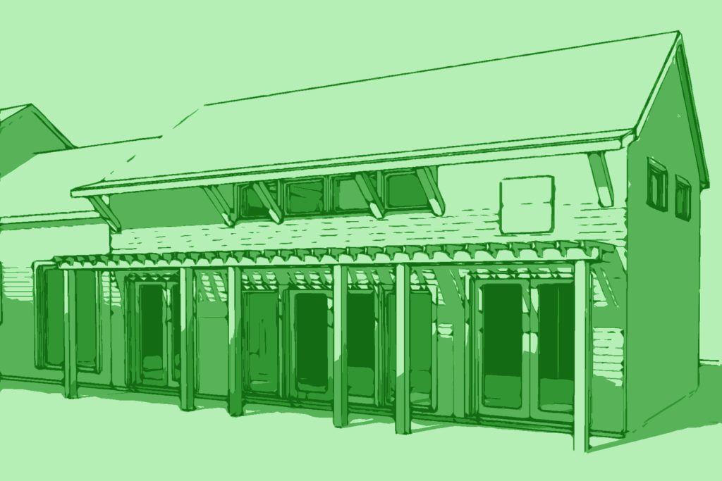
 As you might remember, we have eight different phases to our design process, but not all phases are necessary for every design project. The most important phase of any project is the Construction Document phase. The documents created during this period are the final drawings that your General Contractor (GC) will use to pull the building permit for your project with the local building department, and they are the final document the GC will use to construct your project. There are 6 key drawing types for residential construction documents. Depending on the scope of work required for your project, some or all of these drawings will be used.
The 6 Major Drawing Types
We started putting pen to paper during the PD phase (link) by field measuring the house and creating an existing conditions model in our 3D design software. We then created our Schematic Design (link) during the SD Phase. These drawings were either done by hand, traced over the existing condition drawings or set up in the model. From there the design gets solidified during the design development phase. The DD phase (link) signifies the start of the working drawings, where we start taking the design to the next level and determining how we will build the structure.
Once the base design development drawings are completed and approved by the client, we now enter the construction documents phase and start organizing the project into a series of drawing types. Each drawing type represents accurate information regarding the project and together as a package become the final construction document set.
Types of Drawings:
Plans:
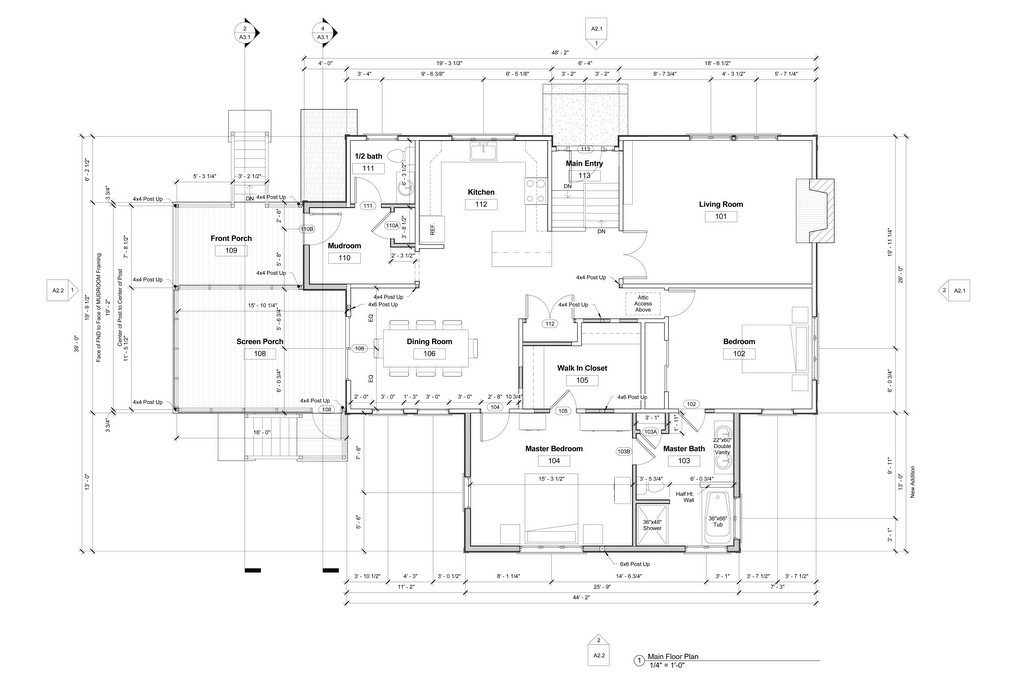 These are the typical drawings for any project. Most projects will have a site plan, floor plans, roof plan and reflected ceiling plans. The best way to describe these drawings is to visualize a horizontal view either cut through the house at each floor level, creating a floor plan, or a horizontal view from above the building, creating a roof or site plan. To create a reflected ceiling plan, the designer will create the cut through a floor plan, and instead of looking down, the view looks up at the ceiling and will indicate where light fixture, ceiling level changes and molding locations in each room.
Exterior & Interior Elevations:
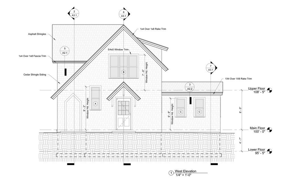 An exterior elevation is a straight on look at one of the sides of the building from the outside. This view will show the exterior shape of the house and will indicate, floor to floor heights, the overall heights of the building, openings in the exterior walls, be it doors or windows, the location of the grade as it relates to the house and the different materials and products used on the outside. Interior elevations are similar to exterior elevations, in that you are in a particular room and looking at each wall within the space. The interior elevation would indicate the overall height of the room, openings in the walls, the extent of finishes, cabinetry and locations of other elements mounted to the walls.
Building & Wall Sections:
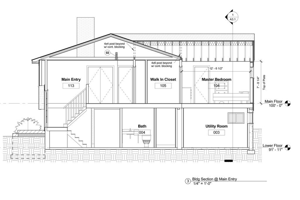 Similar to how a plan is sliced horizontally through the house, a building section is a vertical cut through the house. Just like an interior elevation, a section shows the different rooms it is cut through. The primary purpose of a section drawing is to indicate the structure of the house, vertical dimensions, and general materials all the way from the footings of the foundation, all the way to the top of the roof.
A wall section will be larger in scale and will focus on one wall location to better understand how it is put together and the materials needed to do so.
Exterior & Interior Details:
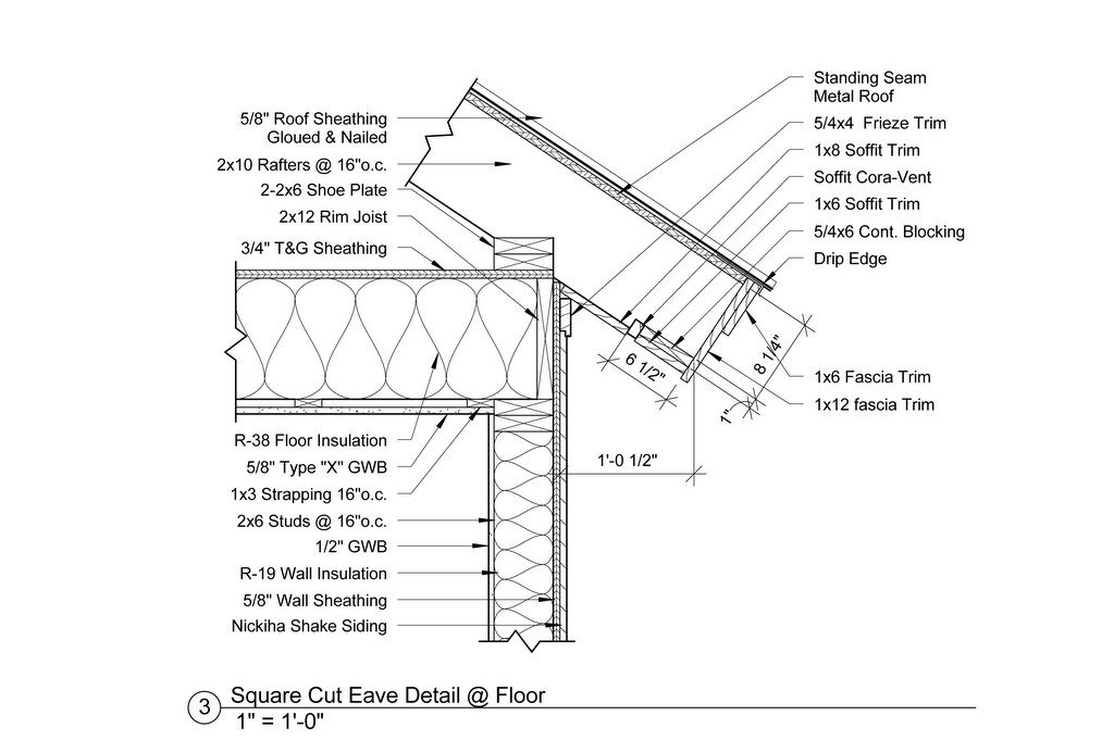 All of the above drawing types are large drawing types. Exterior and interior details are when we start to zoom into specific areas of the house and indicate the materials of that detail and any other specific information need to construct it. Details are created from a horizontal cut, vertical cut or elevation of a particular area of the house.
Schedules & Room Finishes:
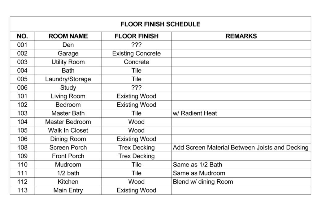 A schedule is used to indicate different information about a product or a material all in one place. For instance, if you have multiple floor levels in your house and doors into each of the rooms, you will need a door schedule to indicate all of the information for the doors on one drawing. With a schedule, you will be able to see the total amount of doors, the different types of doors, where they are located, the material that each door is made from and the hardware needed for each door. A schedule can be used for a multitude of items. In addition to doors, windows, room finishes, cabinetry, plumbing fixtures, and appliances are usually included on schedules.
Framing & Utility Plans:
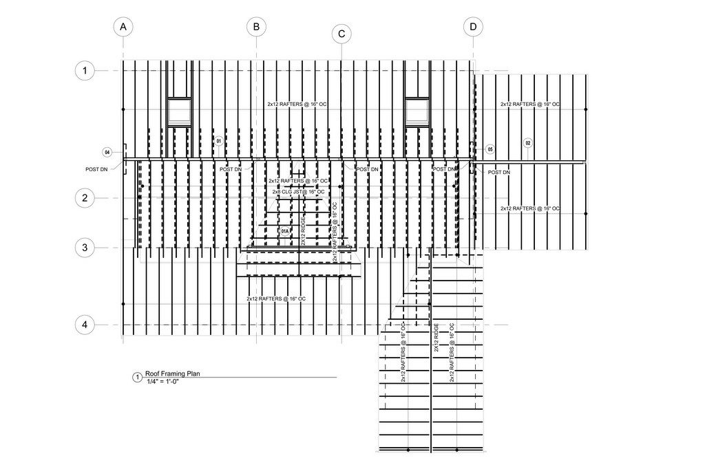 Framing plans are the structural drawings for residential projects. They are mostly used to indicate the floor and roof framing members of the project. The information shows the builder the size of the material and where the weight acting on the framing members will be located. The weight of the framing members, the items and people within the house are considered “loads.” A dead load is the weight of the materials that make up the building and live load is the furniture and occupants of the house. These loads have to transfer all the way through the building down to the foundation. We generate utility plans to indicate the items for the major trades of the project. They will show the location of all plumbing fixtures as well as appliance and electrical requirements for the project.
Completing The Drawing Set
Obviously this is a lot of information to digest for one blog post, but it is precisely the work that needs to be completed for a residential design project. All of this information, collected over the length of the design process, is detailed within the construction drawings so the general contractors will have everything they need to build your project. All of the different drawing types need to reference back and forth with each other, so nothing gets lost during construction. A floor plan will have a symbol on it indicating where a section cut is made through the house. The symbol is also located on the exterior elevation drawings. When looking at the building section drawing, it could have other symbols of certain areas indicating a wall section or a detail. When looking at framing plans, there are symbols used for each individual beam in the house. That symbol will have a number referenced to a beam schedule, showing all the beams in the project, the size of the beam and any comments relative the beam and how it is to be framed.
Hopefully, this will give you a better understanding of how the sequence of the construction documents starts with an overall understanding of the project in a broad sense and works its way down into specific areas of the house and how the building is constructed. Making a building stand up on paper is one thing, but seeing the look on the homeowner’s face while the contractor is building their dream from our drawings makes it all worthwhile. Have you ever done a construction project on your house? If so we would love to hear about your experience.